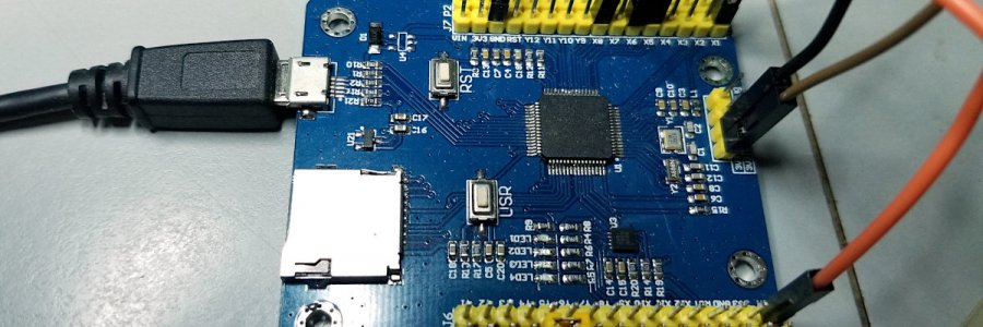
After tinkering with the Adafruit Trinket M0 for a short while I ordered a STM32F4 MicroPython board from icstation.com. When I got it I dropped it in a box and forgot about it for a year or so. When I finally went to play with the board I saw that it had "TPYBoard" printed on the back, so I googled for info and found nothing but page after page of Chinese, except a very few pages of English that weren't very much help. But they helped enough that I finally got it working in a very basic way, blinking some LEDs and such, but still couldn't find any English docs.
Then in one of my google search sessions I fumbled on the PYBoard and realized that the TPYBoard is a clone PYBoard. Aha! I had never heard of the PYBoard before (wasn't paying attention when I looked at the MicroPython website). It has quite a powerful little microcontroller onboard - it's a 168MHz STM32F405RG Cortex M4 ARM chip, with 1MB of flash and 192k of RAM. There's an Micro SD slot to expand storage. It has hardware floating point. There are 24 GPIO pins available. Since it's an ARM micro the chip has lots of very nice peripherals - you can look them up yourself. The onboard PYB library has support for them all. The board also has a MMA7660 3-axis accelerometer onboard.
The board has a micro-USB port. When you plug that cable into your computer the PyBoard shows up as a USB drive with some files in it. One of these files is called main.py. To change the default blinky LED program you edit that file and save it back to the board. Then reset the board and your new program runs.There are other more advanced ways to run programs, but that's the basic way. You can use any terminal program to control the board and use as an output display. I run Linux and use 'screen' in the terminal. Works great. I used Picocom briefly before switching to screen - worked fine as well, but I'm more comfortable in screen. I've also used Putty on a windows box - a bit clunky, like most windows software, but works just fine.
Now I finally had all the documentation I needed to get going properly. Their docs aren't super great. They tend to be a bit vague on details, but they're adequate, and if you have any experience with other microcontroller boards and a bit of a clue about Python (or really any programming language - they're all pretty similar, except for maybe Perl) you can figure it out with some trial and error. The PYBoard definitely isn't as easy to get started on as the Adafruit Trinket, but it's a whole lot more capable.
BTW: The board they're selling now is a bit different than the one I bought - it appears to be just a slightly larger board - different color - and laid out a bit differently. I think the differences are all cosmetic, but I don't own one, so I don't know for sure.
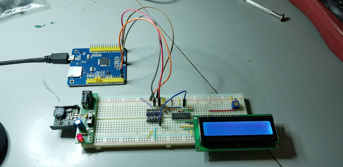
For my first real project after the obligatory LED blinkings I tried to drive my Shift-1 one-wire LCD circuit. I spent a couple evenings fiddling with it and writing code - and refreshing my long gone Python programming knowledge. I hadn't looked at Python in a very long time and had forgotten pretty much everything. Had to connect my trusty Saleae logic analyzer to find out why my code wouldn't work. It was 100% because of my complete noobness in Python. Finally got the code outputting pulses the way it should, but the LCD still wouldn't work. Turns out that, though the PYBoard processor is fast, a high level language like MicroPython just can't do 1uS delays. About the lowest it can go is 16uS. I removed the delay and got down to 6uS. Not good enough. The only cure would be to write the output function in assembly. I didn't want to tackle ARM assembly language right then, and the board has lots of I/O (a one-wire LCD isn't necessary), so I left this project right there for now.
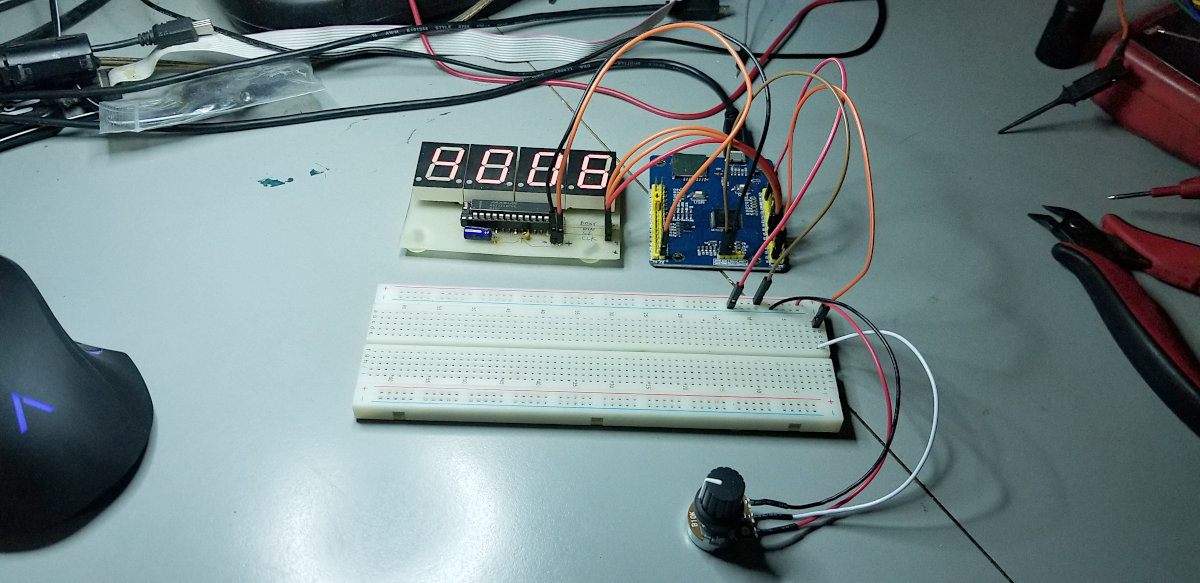
Next thing I tried was to connect up my ancient home etched MAX7219 7-segment LED board. Code for this was ridiculously easy, though it took me quite a while, once again because of my way beyond rusty Python "skills". I had to use the logic analyzer to find out that the PYB library doesn't manage the CS line (at least as far as I was able to tell - the docs are somewhat vague). No problem, I just put in some code to control it myself, and the display lit up and worked.
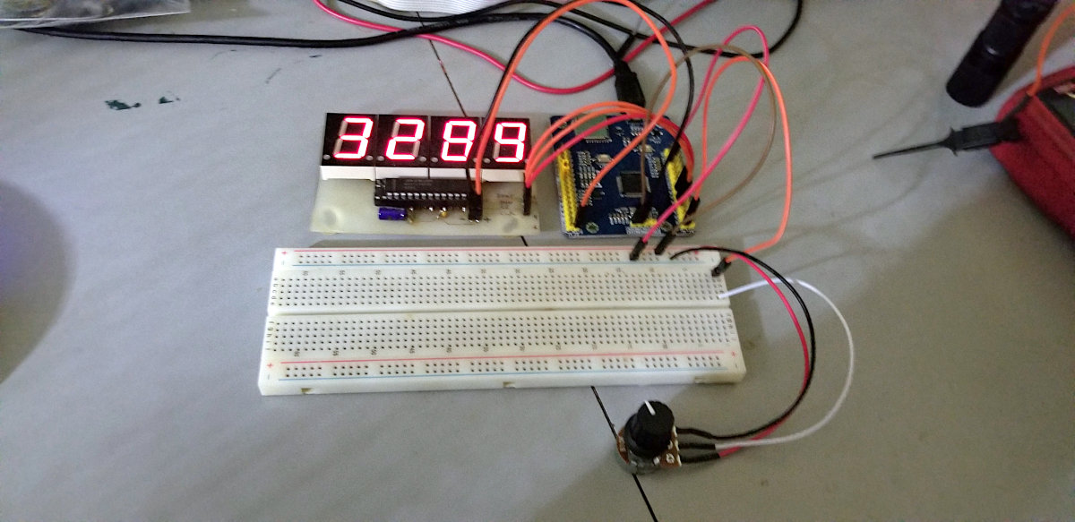
Then I added a 10K pot and wrote some code to read it with an ADC pin and display the ADC value on the LED display. Once again, super easy to code. The only reason it took me some hours is that I was relearning Python as I wrote code. I'd type in my incorrect C-like Python code - it wouldn't work - I'd look up how to do that properly in Python and change it and it would work - off to fix the next bug.
So far I'm very impressed with it. More projects coming soon, and some code examples. I'm thinking of maybe dragging one of my ancient robot chassis out of the junk pile and having a play. Maybe build a balancing robot - had no success the first time I tried that.
Here's the basic SPI code. Super simple:
from pyb import SPI
cs = pyb.Pin('X5', pyb.Pin.OUT_PP)
cs.high()

spi = SPI(1, SPI.MASTER, baudrate=460800, polarity=1, phase=0)

#initialize
cs.low()
spi.send(b'\x0a')
spi.send(b'\x0f')
cs.high()
cs.low()
spi.send(b'\x0b')
spi.send(b'\x03')
cs.high()
cs.low()
spi.send(b'\x09')
spi.send(b'\x0f')
cs.high()
cs.low()
spi.send(b'\x0c')
spi.send(b'\x01')
cs.high()

dig1 = dig2 = dig3 = dig4 = 0

while True:
    cs.low()
    spi.send(b'\x01')
    spi.send(dig1)
    cs.high()
    cs.low()
    spi.send(b'\x02')
    spi.send(dig2)
    cs.high()
    cs.low()
    spi.send(b'\x03')
    spi.send(dig3)
    cs.high()
    cs.low()
    spi.send(b'\x04')
    spi.send(dig4)
    cs.high()

    dig4 += 1
    if dig4 > 9:
        dig4 = 0
        dig3 += 1
    if dig3 > 9:
        dig3 = 0
        dig2 += 1
    if dig2 > 9:
        dig2 = 0
        dig1 += 1
    if dig1 > 9:
        dig1 = 0
    pyb.delay(50)