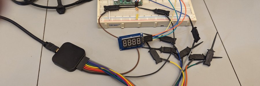
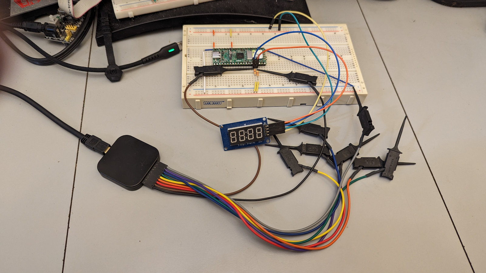
So I ported some my old (working) MicroPython TM1637 code over to the Milk-V Duo and... it wouldn't work. Then, out of the blue, it worked, one time, and then never worked again. Very weird, because I could look at the output with the logic analyzer and it looked fine. Well... as fine as it's possible to look - the TM1637 protocol is like backward i2c (LSB first) with no address. So in the logic analyzer it doesn't decode properly. You have to just read the DIO pulses (bits) on the screen backward to see what it's doing.
I spent SO many hours trying all kinds of things, and looking at various TM1637 library source code - they were all doing pretty much the same thing I was. Nothing worked and I had no clue why.
Finally I looked at someone's source and they did something a little bit different. I tried it in my code and the display lit up and worked.
Here's what I found. In my TM1637 init() I was doing this:
void init(void){      //initialize TM1637
  start();
  byteout(0x40);      //write data to display register, auto address, normal
  byteout(0x8c);      //display on - brightness (0x88 to 0x8f)
  stop();
}
On a slower MCU that works just fine, but the TM1637 wants a little time to process the 0x40 before you hit it with the 0x8c, and the Milk-V Duo is clocked pretty fast. I found that I could either add a stop() and a start() between bytes:
  void init(void){      //initialize TM1637
  start();
  byteout(0x40);      //write data to display register, auto address, normal
  stop();
  start();
  byteout(0x8c);      //display on - brightness (0x88 to 0x8f)
  stop();
}
or a short delay:
void init(void){ //initialize TM1637
start();
byteout(0x40); //write data to display register, auto address, normal
usleep(1000); //could probably be shorter - haven't tested
byteout(0x8c); //display on - brightness (0x88 to 0x8f)
stop();
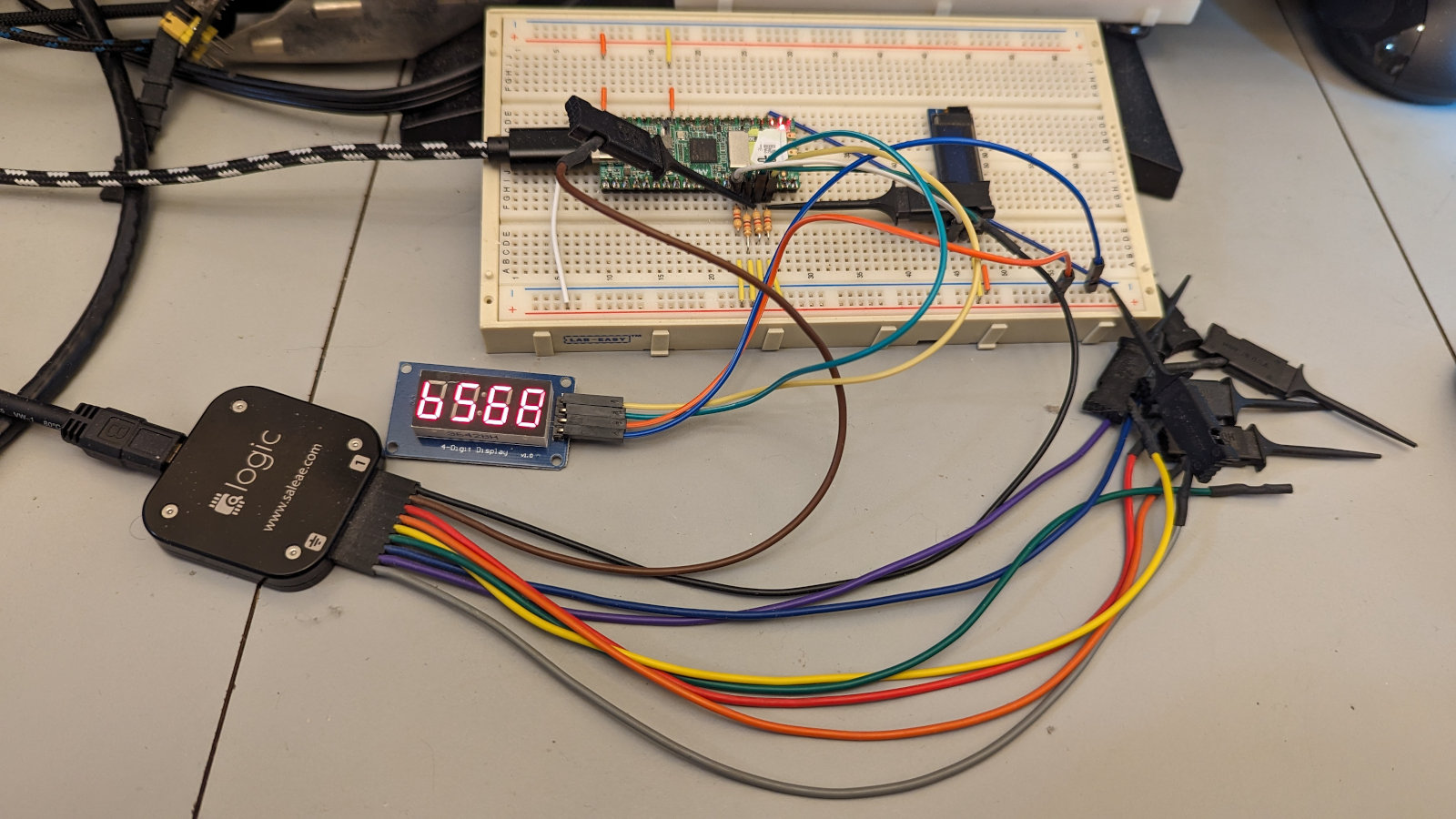
}and the display now works perfect. Whew! That took WAY too long to figure out.
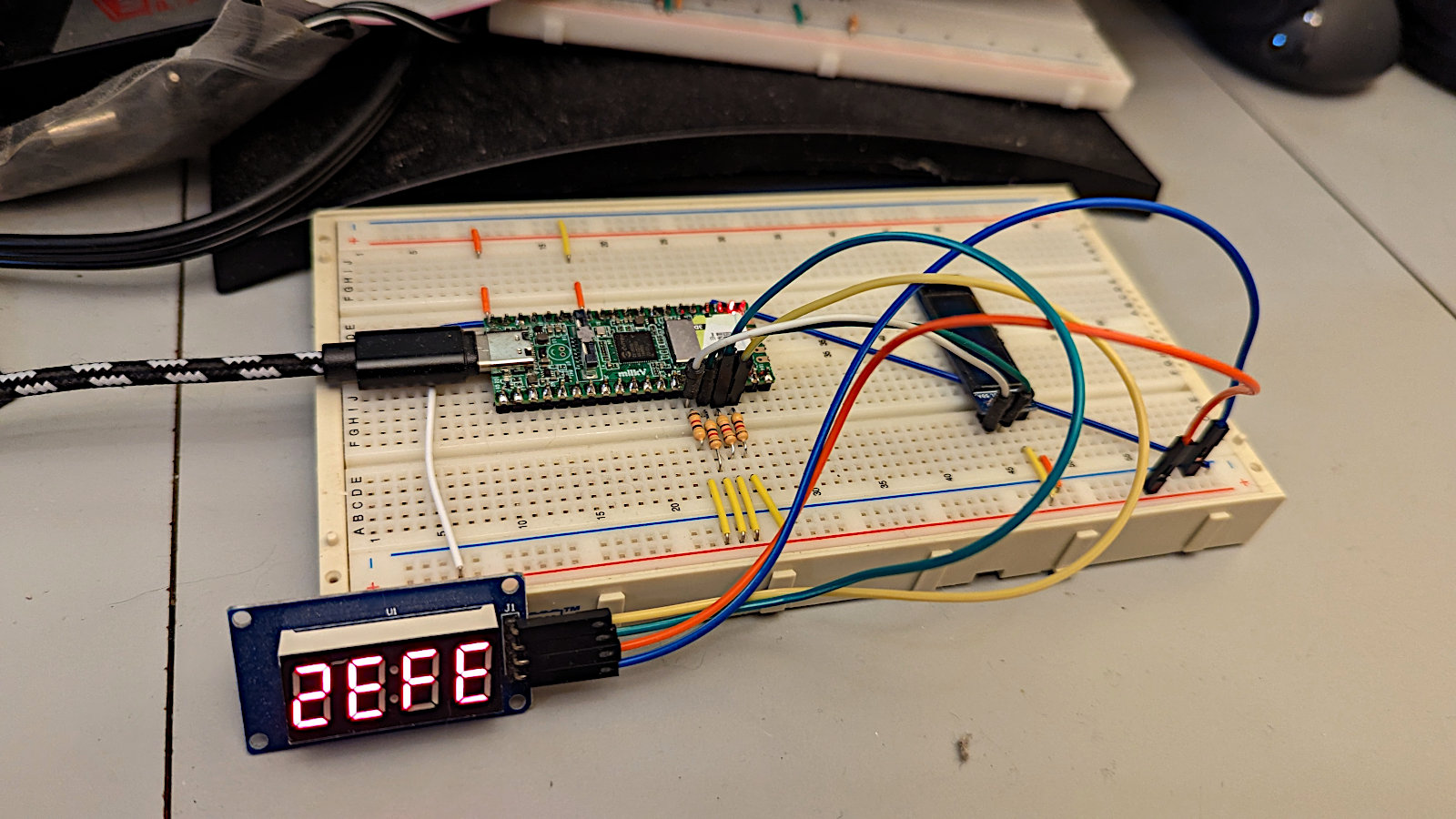
I'm using pins 16 and 17 to control the TM1637. When the Milk-V Duo reboots it defaults to having those pins set as UART. To make the pins GPIO so my program will work means pin_muxing them to GPIOs. WiringX should do that for me, but it doesn't yet - they're working on it. I use a tiny shellscript to run the program. It sets the two pins to GPIO and then runs the program:
cvi_pinmux -w UART0_TX/XGPIOA_16
cvi_pinmux -w UART0_RX/XGPIOA_17
./tm1637_4digit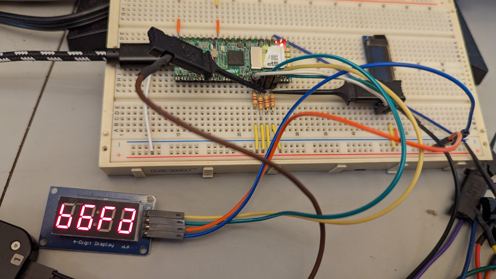
tm1637_4digit.c
#include <unistd.h>
#include <wiringx.h>
#include "tm1637_4digit.h"

int dio = 16;
int clk = 17;

// 0,1,2,3,4,5,6,7,8,9,a,b,c,d,e,f,h,l,p,3-lines,blank
unsigned char font[22] = {0x3f,0x06,0x5b,0x4f,0x66,0x6d,0x7d,0x07,0x7f,0x6f,0x77,0x7c,0x39,0x5e,0x79,0x71,0x76,0x38,0x73,0x49,0x00};
int div[5] = {0x1000,0x100,0x10,0x01};
int digit[5] = {0,0,0,0};

int main(){
  if(wiringXSetup("duo", NULL) == -1) { //wiringx initialize
    wiringXGC();
    return -1;
  }

  pinMode(dio,PINMODE_OUTPUT);  //set up dio & clk pins
  pinMode(clk,PINMODE_OUTPUT);
  digitalWrite(dio, LOW);       //dio == 0 when set as output
  digitalWrite(clk, LOW);       //clk == 0 when set as output
  pinMode(dio,PINMODE_INPUT);   //dio pin high
  pinMode(clk,PINMODE_INPUT);   //clk pin high

  init();                       //initialize TM1637

  help();                       //print HELP
  sleep(3);

  while(1){                     //print $0000 to $ffff
    for(int x=0;x<0x10000;x++)
      hexconv(x,0,0);
  }
}

//display 4-digit number in hex
void hexconv(int num,int leadzero,int colon){
  int x;
  for(x=0;x<4;x++){
    digit[x] = num / div[x];
    num = num - (digit[x] * div[x]);
  }
  if(leadzero == 0)
    leadz();
  start();
  byteout(0xc0);
  for(x=0;x<4;x++){
    if(x == 1 & colon == 1)
      byteout(font[digit[x]] + 0x80);
    else
      byteout(font[digit[x]]);
  }
  stop();
  usleep(50);
}

void leadz(void){                   //suppress leading zeroes
  int x;
  for(x=0;x<4;x++){
    if(digit[x] != 0)
      return;
    else
      digit[x] = 20;
  }
}

void byteout(unsigned char cmd){    //write one byte to TM1637
  int x;
  unsigned char ack;
  for(x=0;x<8;x++){                 //clock out cmd byte
    pinMode(clk,PINMODE_OUTPUT);    //clk low
    usleep(50);
    if(cmd & 0x01)                  //set data bit
      pinMode(dio,PINMODE_INPUT);   //dio high
    else
      pinMode(dio,PINMODE_OUTPUT);  //dio low
    usleep(50);
    pinMode(clk,PINMODE_INPUT);     //clk high
    usleep(50);
    cmd >>= 1;                      //rotate next bit into position
  }
  pinMode(clk,PINMODE_OUTPUT);      //do 9th clock pulse - clk low
  pinMode(dio,PINMODE_INPUT);       //dio input
  usleep(25);
  pinMode(clk,PINMODE_INPUT);       //clk high
  usleep(25);
  ack = digitalRead(dio);           //read the ack/nack
  if(ack == 0)
    pinMode(dio,PINMODE_OUTPUT);
  usleep(50);
  pinMode(clk,PINMODE_OUTPUT);      //clk low
  usleep(50);
}

void start(void){
  pinMode(dio,PINMODE_OUTPUT);  //dio low
  usleep(50);
}

void stop(void){
  pinMode(dio,PINMODE_OUTPUT);  //dio low
  usleep(50);
  pinMode(clk,PINMODE_INPUT);   //clk high
  usleep(50);
  pinMode(dio,PINMODE_INPUT);   //dio high
  usleep(50);
}

void brightness(unsigned char level){       //0 - 7
  level = level + 0x88;
  start();
  byteout(level);               //display on - brightness
  stop();
}

void init(void){      //initialize TM1637
  start();
  byteout(0x40);      //write data to display register, auto address, normal
  stop();
  start();
//  usleep(1000);
  byteout(0x8c);      //display on - brightness (0x88 to 0x8f)
  stop();
}

  void help(void){    //display HELP
  start();
  byteout(0xc0);
  byteout(font[0x10]);
  byteout(font[0x0e]);
  byteout(font[0x11]);
  byteout(font[0x12]);
  stop();
}
tm1637_4digit.h
void help(void);
void hexconv(int,int,int);
void leadz(void);
void byteout(unsigned char);
void start(void);
void stop(void);
void brightness(unsigned char);
void init(void);