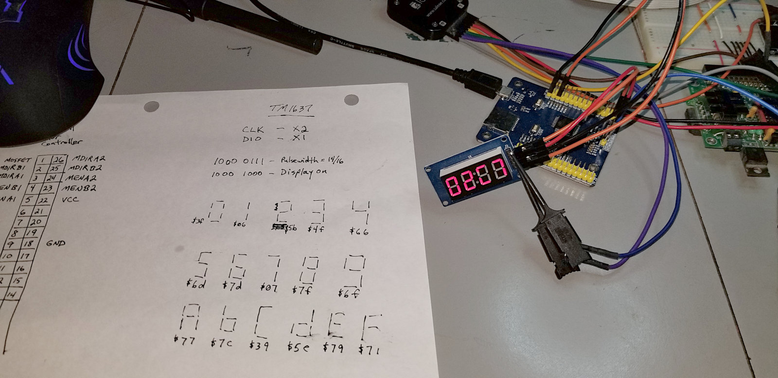
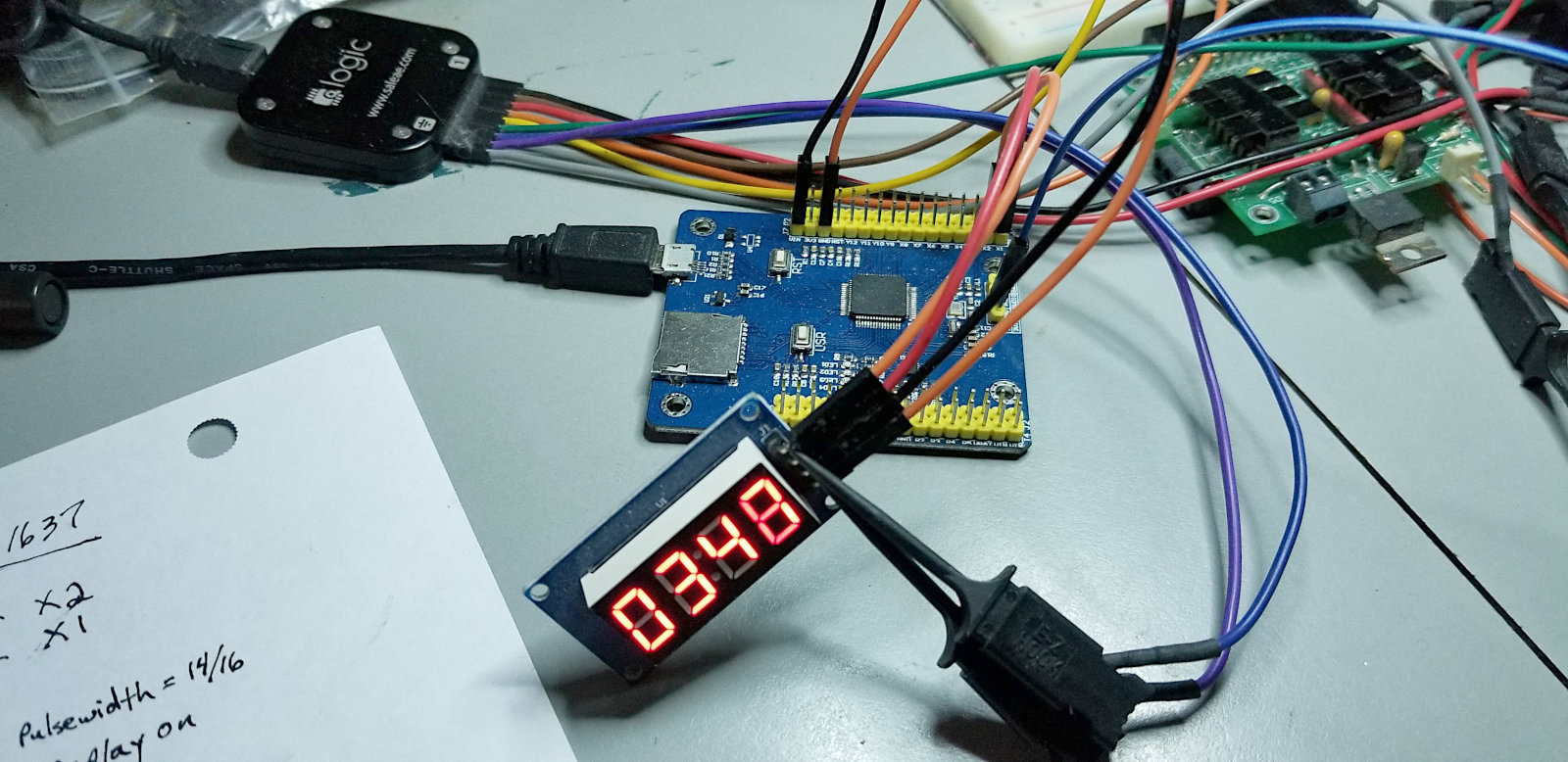
I wrote some code for the PyBoard to drive a TM1637 4-digit 7-segment LED display. The code is basically I2C with no slave, so not terribly difficult to bit-bang.
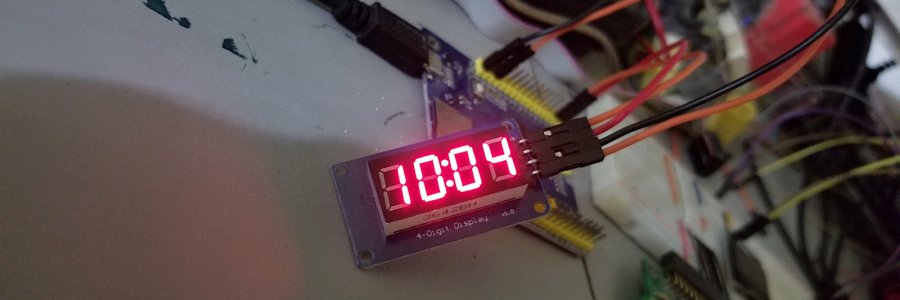
Then I modified that code to use the PyBoard's RTC to work as a clock. That worked fine, so I thought I would get it going on the Trinket M0. Worked away at the code for a while before realizing that the Trinket M0 doesn't have an RTC. So I ditched that idea and just got the display working on the Trinket M0.
I had gotten fairly comfortable with MicroPython and the PYB library on the PyBoard. Porting my code to CircuitPython on the Trinket M0 and the Adafruit libs was different enough that I basically had to start learning all over again. The libs are quite different
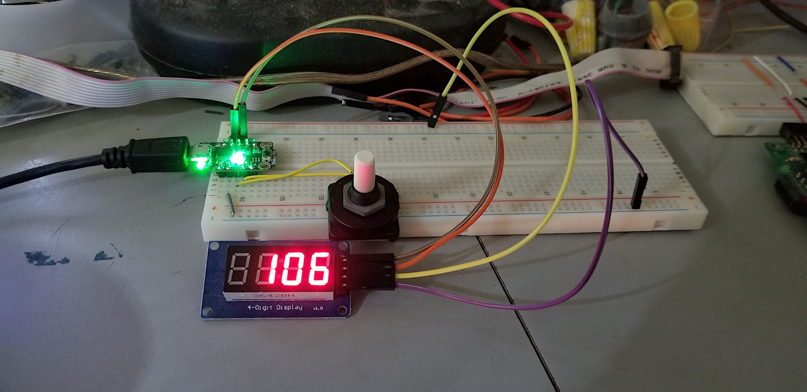
In this pic I'm using a quadrature encoder to increment and decrement a counter, and displaying the number on the TM1637. Adafruit hasn't implemented any interrupts in CircuitPython yet, so the encoder has to be polled. There is a method of doing fast pseudo-interrupt polling that I might play with later

Here's the PyBoard TM1637 demo code:
from pyb import Pin
import time

CLK = Pin('X2',Pin.IN,Pin.PULL_UP)
DIO = Pin('X1',Pin.IN,Pin.PULL_UP)
CLK.low()
DIO.low()

# 0,1,2,3,4,5,6,7,8,9,a,b,c,d,e,f,h,l,p,3-lines,blank
font = [0x3f,0x06,0x5b,0x4f,0x66,0x6d,0x7d,0x07,0x7f,0x6f,0x77,0x7c,0x39,0x5e,0x79,0x71,0x76,0x38,0x73,0x49,0x00]
div = [0x1000,0x100,0x10,0x01]
digit = [0,0,0,0]

def help():
    start()
    byteout(0xc0)
    byteout(font[0x10])
    byteout(font[0x0e])
    byteout(font[0x11])
    byteout(font[0x12])
    stop()

#display 4-digit number in hex - use bool to select leading zero
def hexconv(num, leadzero, colon):
    for x in range(4):
        digit[x] = int(num / div[x])
        num = num - (digit[x] * div[x])
    if leadzero == 0:           #if leading zero deselected
        leadz()                 #go blank them
    start()
    byteout(0xc0)               #set data address
    for x in range(4):
        if x == 1 and colon == 1:
            byteout(font[digit[x]] + 0x80)
        else:
            byteout(font[digit[x]])
    stop()

def leadz():                    #clear leading zeros
    for x in range(4):
        if digit[x] != 0:
            return
        else:
            digit[x] = 20

def byteout(cmd):
    for x in range(8):                          #clock out cmd byte
        CLK = Pin('X2',Pin.OUT_PP)              #clk low
        time.sleep_us(50)
        if cmd & 0x01:                          #set data bit
            DIO = Pin('X1',Pin.IN,Pin.PULL_UP)  #dio high
        else:                                   #or
            DIO = Pin('X1',Pin.OUT_PP)          #dio low
        time.sleep_us(50)
        CLK = Pin('X2',Pin.IN,Pin.PULL_UP)      #clk high
        time.sleep_us(50)
        cmd = cmd >> 1                          #rotate next bit into position
    CLK = Pin('X2',Pin.OUT_PP)              #do 9th clock pulse
    DIO = Pin('X1',Pin.IN)                  #dio input
    time.sleep_us(50)
    CLK = Pin('X2',Pin.IN,Pin.PULL_UP)      #clk high
    while DIO.value() != 0:                 #wait for ack
        pass
    DIO = Pin('X1',Pin.OUT_PP)              #dio output
    time.sleep_us(50)
    CLK = Pin('X2',Pin.OUT_PP)              #clk low
    time.sleep_us(50)

def start():
    DIO = Pin('X1',Pin.OUT_PP)              #dio low
    time.sleep_us(50)

def stop():
    DIO = Pin('X1',Pin.OUT_PP)              #dio low
    time.sleep_us(50)
    CLK = Pin('X2',Pin.IN,Pin.PULL_UP)      #clk high
    time.sleep_us(50)
    DIO = Pin('X1',Pin.IN,Pin.PULL_UP)      #dio high

def brightness(level):  # 0-7
    level = level + 0x88
    start()
    byteout(level)      #display on - brightness
    stop()

def init():
    start()
    byteout(0x40)   #write data to display register, auto address, normal
    stop()
    start()
    byteout(0x8c)   #display on - brightness (0x88 to 0x8f)
    stop()

#------------------------------------------------------
# Begin here
#------------------------------------------------------

init()

help()
pyb.delay(5000)

while True:
    for x in range(0x10000):
        hexconv(x,0,0)

