I was recently looking at Microchip's PIC10F322 microcontroller and thought it was a very capable little MCU for its price (and size). It has some really interesting peripherals onboard, like the Configurable Logic Cell (CLC), the Numerically Controlled Oscillator (NCO) Module and the Complementary Waveform Generator (CWG). I don't even know what they do, but that's what makes them interesting. :D The chip has four I/O pins (one of which is input-only), two 10-bit PWMs, three 8-bit A/D channels, a fixed voltage reference (FVR) and two 8-bit timers. It can be internally or externally clocked as fast as 16MHz, but you would have to use one of only four I/O pins (RA1) for external, so for most purposes that wouldn't be very useful. The chip has 512 words of program memory and 64 bytes of SRAM
10F322s are available in teeny tiny little SOT23-6 packages or in 8-pin DIP (with 2 pins unconnected). I bought a bunch of each type, but what I'm really interested in is the SOT23-6 packages. Just for the fun of it I'm designing a teeny tiny general purpose 10F322 board. The board's size is limited by the breadboard pins, not by the components. It will be roughly 3/4" square, plugged into the breadboard vertically, with ICSP pins out the top.
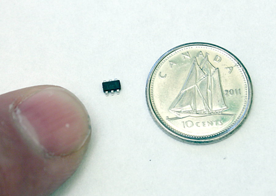
Canadian dime - same size as USA dime. Also, index fingertip for scale. SOT23s are about 1/8" long. They're really not all that hard to solder.
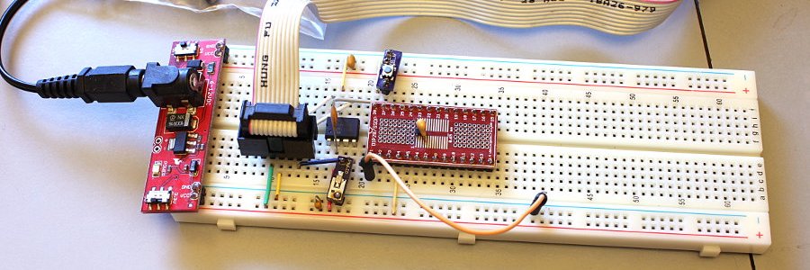
I plugged an 8-pin chip into the breadboard, wired it up and hit my first (small) obstacle. I run SourceBoost's BoostC C compiler, and it does not support any 10F devices at all. I had to go back to writing code in assembly language. I used to love coding in assembly, but now I discovered that I had almost totally forgotten how. My asm coding was super rusty! I've been writing in C (and C-like languages) for too long. Anyway, after writing a few programs and looking at some of my old code the memories come back fairly quickly.
With the help of a couple downloaded blinky programs to help refresh my memory, and a bunch of reading through the datasheet, I soon had LEDs blinking and Timer0 interrupts figured out. Great! On to bigger and better things...
Then, since I wanted a general purpose board, and three of the four IO pins are shared with ICSP, I had to figure out a way to switch out whatever circuit might be connected to those pins so ICSP would still work. My first thought was, "Three SPST switches?! That is gonna suck! There has to be a way to switch those lines out electronically..."
I looked at several methods that might work and then decided to try using Fairchild NC7SZ66 SPST Bus Switches. They come in SOT23-5 packages, so that fits right in with the 10F322 in SOT23-6. I can use one SPST switch to disconnect all three lines to external circuitry for programming and reconnect them to run the program (like an old Motorola 68HC11 board).
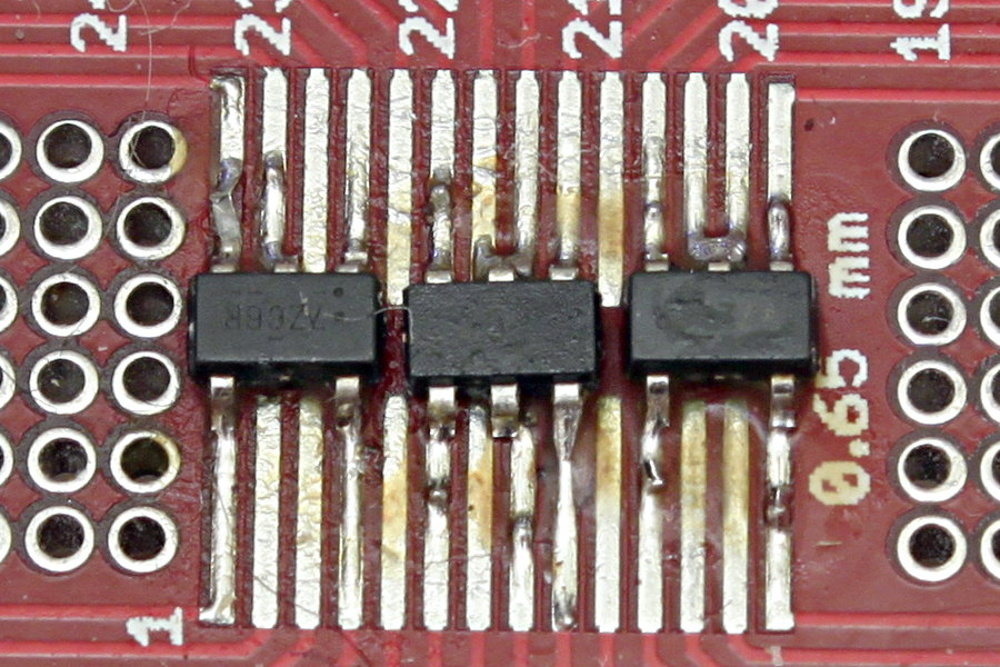
I soldered one NC7SZ66 to a DipMicro DE2698 adapter board. The pitch isn't right, but I found I could catch the four outer pins perfectly and just sort of fake the middle pin onto whichever track the solder chose to flow onto (often both).
The SOT23-5 is under the much larger decoupling cap I soldered on top. On the right is a tiny little blue button on a tiny little PCB and on the left is a tiny little PCB with a LED and resistor on it. Those are Atomsofttech products - MicroSW and tinyLED. Good stuff - big time and space savers for breadboarding. He also makes a pretty nice breadboard power and USB/UART module (with reset switch and LIPO charger) called the Breadboard Buddy Pro (not in the picture).
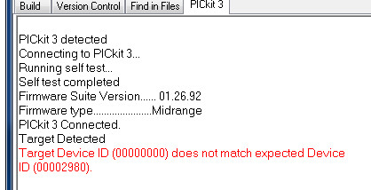
I wired that up and hit obstacle number two. Now my PICKit3 refused to connect. If I remove the wire from VPP (Pin 8) to the adapter board it works. Put it back - doesn't work. Hmmm...
I added decoupling caps all over the place. Didn't help. I shortened the VPP wire to eliminate a step on the breadboard. It worked! Once. Then it wouldn't work anymore.
So that's where I am now. I'm going to put a SOT23-6 PIC on the adapter board and eliminate the DIP one. Hopefully that will shorten things up enough to cure it...
... Later that day...
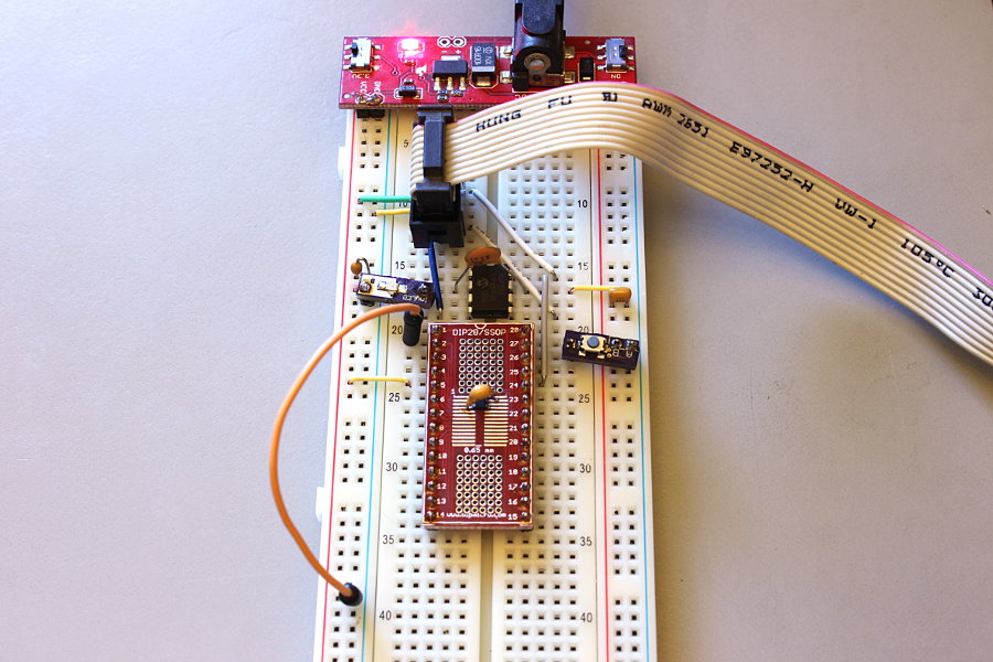
Nope, doesn't help at all. The 10F322 in SOT23-6 is soldered to the adapter board right beside the NC7SZ66.
I'm thinking I'll scrap the bus switch on the RA3/MCLR/VPP line and just go with a diode to protect external circuitry from programming voltage, since RA3 is input-only when it's not acting as VPP.
The bus switches on the RA0/PGD and RA1/PGC lines are a must though. Haven't tested them yet, but I see no reason why they shouldn't work just fine.
... A few days later...
Yup, the diode works fine, and the bus switches work perfect. I soldered a SOT23-6 10F322 to the proto board and another NC7SZ66 bus switch, and got rid of the 8-pin DIP.
Here's my cobby prototype soldering, still covered in flux and cat hair. You can see how the solder on the top middle pin of the left switch flowed onto one pad, but on the PIC and the other switch it flowed onto both. Works just fine either way. Good enough for a quick and dirty prototype (I have real PCBs coming soon)
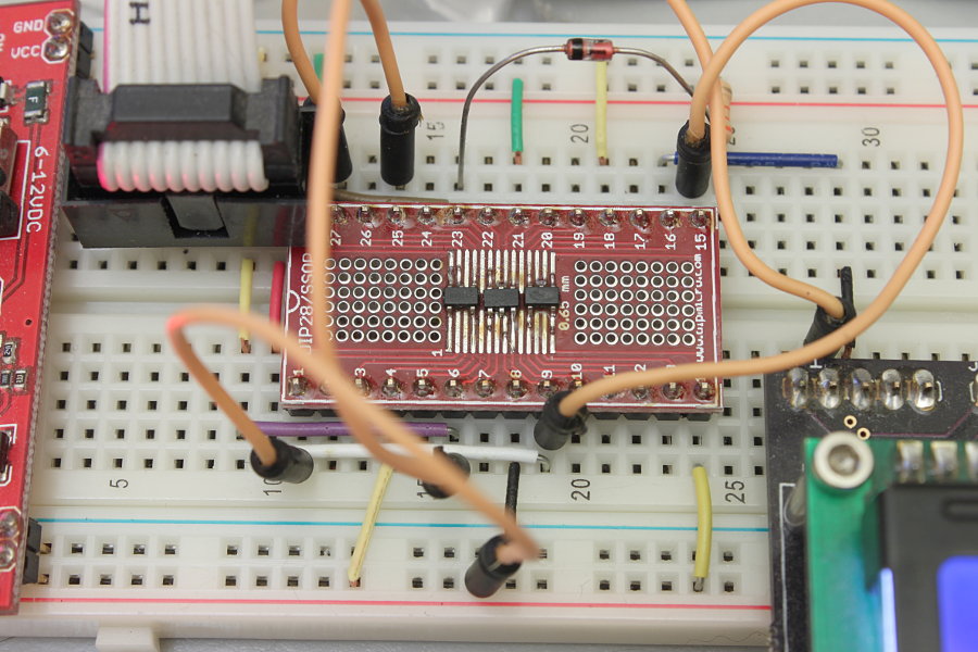
Here's the same pic zoomed out. The orange wire in the foreground, plugged into the 5V rail, is my OE switch to turn the bus switches on and off. To turn them off for programming the PIC I just move the wire to the ground rail. When the bus switches are off any circuitry connected to RA0 and RA1 pins is disconnected so the pins can act as PGD and PGC for programming. Switch the OE wire back to 5V to run the program (I have to power cycle the board because the LCD needs to be initialized.)
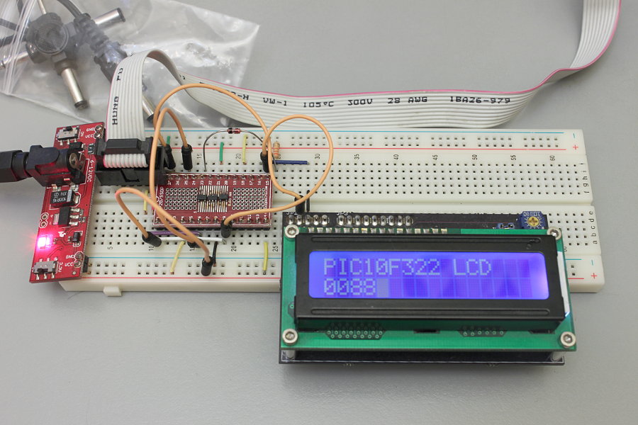
Here I'm using the 10F322's RA0 and RA1 pins to drive my 2-wire LCD. It's counting up through 16 bits, converting that to ascii and displaying hex values. Still have one unused input pin and one output - sweet!
... A few days later...
Here I'm using all four I/O pins - two for the LCD, one for the button and one for the LED.